Free Flight Model Planes
Three Dimensional Motion Analysis of Hi-start Launch of Free Flight Model Gliders
Prepared by Toshimi Taki
October 19, 2023
This article is an English translation of a paper presented at the Aircraft Symposium of the Japan Society for Aeronautical and Space Sciences held in 2022.
DeepL Translator was used for the translation.
Three Dimensional Motion Analysis of Hi-start Launch of Free Flight Model Gliders
by Toshimi Taki
Key Words: Model Gliders, Launching, Lateral Stability, Hook Position
Abstract
Hi-start launching of model gliders is a combination of catapult and towline launching. It uses light rubber and string for the line. This paper presents the three-dimensional motion analysis of the launching. Lateral stability of the launching is studied. The effects of hook position, wing dihedral angle, and vertical stabilizer area on the lateral stability are invstigated.
1. Introduction
Hi-start launching (Figure 1), which uses a light rubber string and a string connected to a line to launch a model glider, was developed in Germany in the 1930s, but has not been used very often for a long time.
In recent years, this method has been adopted as the official F3-RES for Radio Control gliders, and its advantages are being recognized.
Since Hi-start launch has not been studied analytically, equipment specifications and flight adjustment methods rely on experiences. The author reported a two-dimensional motion analysis of a hi-start at last year's Sky Sports Symposium (Reference [2]). In this report, the author presents the details of the method for 3-D motion analysis of hi-start launch and the results of stability analysis during launch.
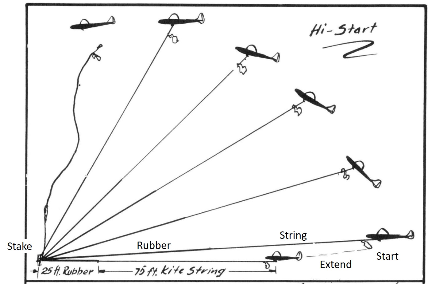
Fig. 1 Hi-start Launch (Ref.[1])
2. Hi-start Launch
2.1 Description of Hi-start Launch
Figure 2 shows the hi-start launching equipment used by the author. For ease of availability, #18 rubber bands are used to make a 7.5 meter rubber string. #3 or #4 nylon fishing line with 22.5 meter length is connected to the rubber string. A triangular prism made of styrofoam sheet is used as a marker. The model gliders weigh 20 to 80 grams are released at an altitude of about 20 meters. The wing spans of the gliders are 400 to 800 mm. This setup is sufficient to fly a small gliders with a wing span of 400 to 800 mm in a narrow space.
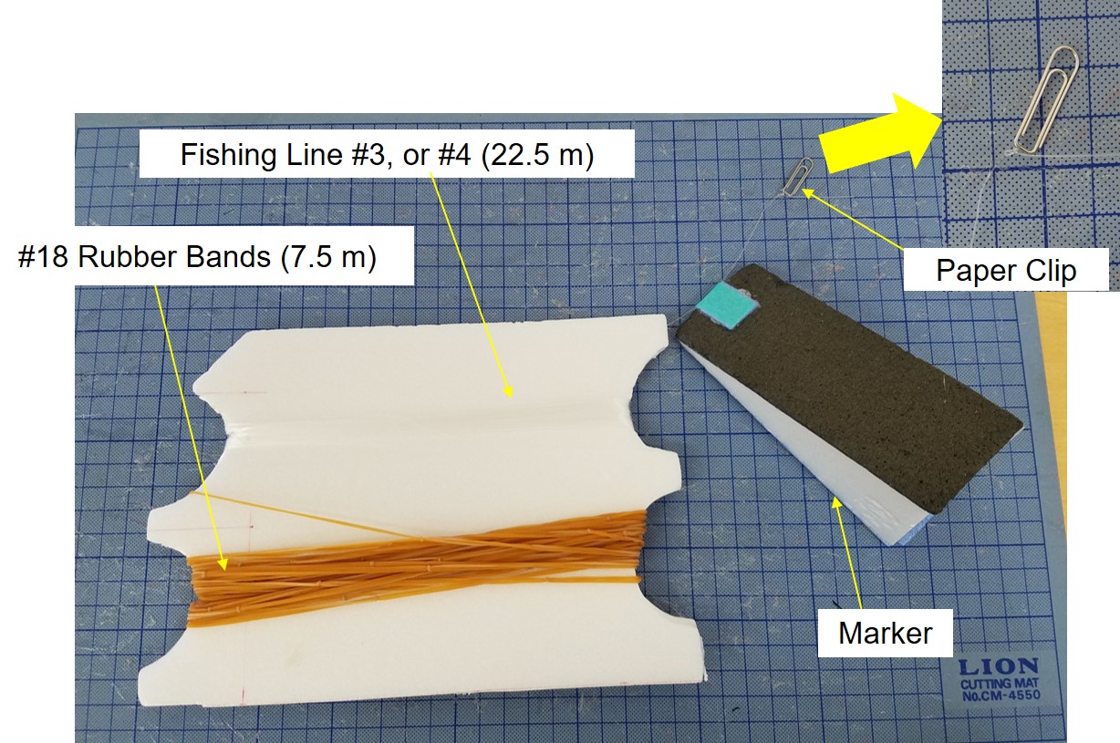
Fig. 2 Equipment of Hi-start Launch
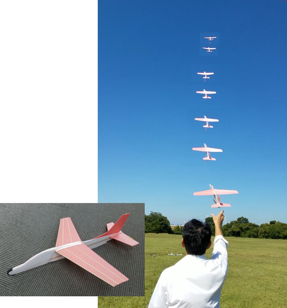
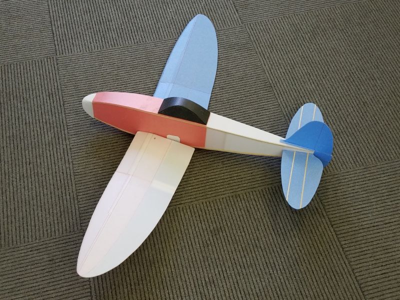
Fig. 3 Hi-start Launch of T-4 Semi-scale Glider
2.2 Advantages of High-start Launch
The advantages of a hi-start launch are as follows.
- While a towing launch requires an assistant, a hi-start launch allows a single person to launch the glider.
- The launching speed is lower than that of hand-throwing or catapult launching, and the glider can be adjusted more easily. The strength and rigidity requirements for the airframe are less stringent.
- There are no restrictions on the size of the glider.
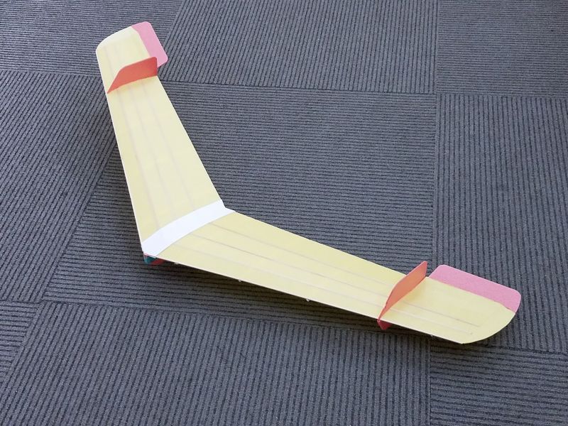
- Any type of aircraft (tailless, canard, etc.) can be launched.
2.3 Problems
The following are the problems of hi-start launching.
- The relationship between the size (mass) of the glider and the specifications of the appropriate setup (rubber strength, rubber length and string length) relies on experience.
- There is no knowledge of the stability of the aircraft during launch.
In particular, knowledge of the relationship between the appropriate hook position and the aerodynamic characteristics of the glider.
3. Analysis Method
3.1 Assumptions for Analysis
The following assumptions are used in the analysis.
- The aerodynamic drag of the line (rubber and string) is ignored. Therefore, deflection of the line due to drag force is ignored.
- Ignore the inertia force of the line.
- Consider the deflection of the line due to gravity.
- The aerodynamic drag and gravity of the marker are considered to act on the hook position.
- Ignore the inertia force of the marker because it is much smaller than the aerodynamic drag force.
- Consider the offset of the hook from the center line of the model glider.
- Ignore wind.
3.2 Deformation and Tension of Line
To analyze the motion of a glider during hi-start launch, the magnitude and direction of the force acting at the end of the line are necessary.
As shown in Figure 4, the author derived the formulas for the tension (T) and its direction (angle phi) of the line when one end of the line is fixed to the ground (the origin of the ground coordinate system) and the other end is attached at the hook of the glider. It is assumed that the line is always in the plane perpendicular to the ground even if the glider moves.
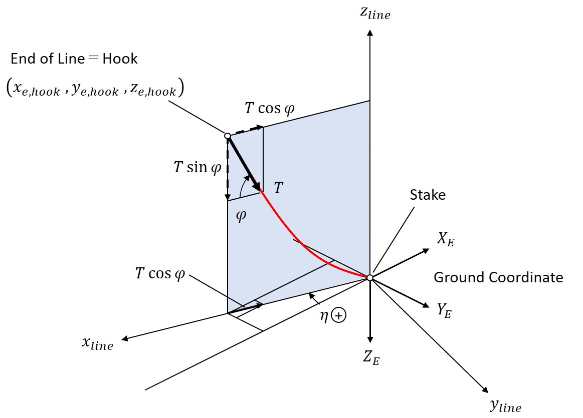
Fig. 4 Deformation and Tension of Line
3.2.1 Analysis Model
Consider the coordinates of the line shown in Figure 5. The elastic deformation of rubber exhibits material nonlinearity, and the deformation of the line is so large that it becomes a geometrically nonlinear problem. To solve this problem, the principle of minimum potential energy is used.
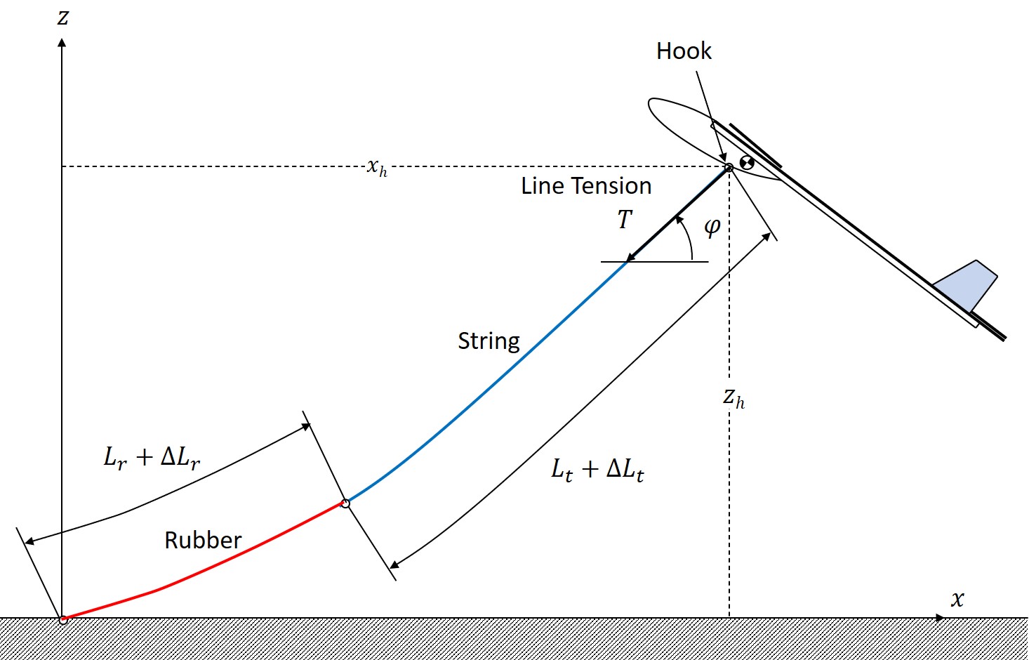
Fig. 5 Coordinate of Line
3.2.2 Solution by the Energy Method
(1) Strain Energy
Consider a portion (element) of the line that is stretched and in a balanced state.
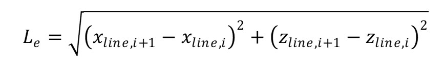
The length of the line is expressed by the following equation.
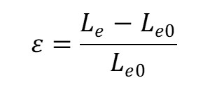
If the original length of this element (in the case of no load) is L_e0, then its nominal strain is expressed as follows.
-- In Case of Rubber
Tension, T is expressed as follows.
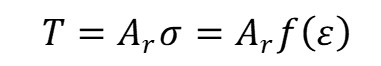
where A_r is the initial cross-sectional area of the rubber, sigma is the stress and f(epsilon) is the stress-strain equation for the rubber, which is obtained experimentally.
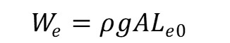
The strain energy is as follows.
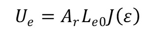
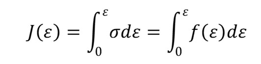
where J(epsilon) is an expression for the strain energy density of rubber and has the following relationship to the stress-strain equation for the rubber.
-- In Case of String
The tension force is as follows.
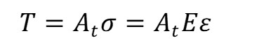
where A_t is the initial cross-sectional area of the string, sigma is the stress, and E is Young's modulus of the string.
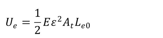
Strain energy of the string is expressed as follows.
(2) Work Done by Gravity
Gravity acting on an element of the line is as follows.
where rho is the density of the line (rubber or string), A is the initial cross-sectional area of the line, and g is the acceleration of gravity.
The work done by gravity on the element of the line (based on the elongated state without gravity (see Figure 6)) is
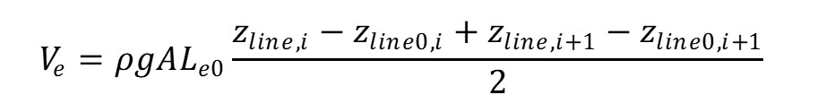

Fig. 6 Work Done by Gravity on an Element of Line
(3) Total potential energy
The total potential energy Pi is expressed by the following equation.
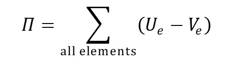
By minimizing the total potential energy, the coordinates of the line in the elongated state with gravity can be obtained, and the tension at the top end of the line and its direction can also be calculated.
The actual minimization calculation is performed using the MS-Excel solver.
3.2.3 Results of Analysis of Line
Figure 7 shows the stress-strain curves obtained from a tensile test of #18 rubber bands. Analysis was conducted on the line with 7.5 m rubber and 22.5 m string (see Figure 2). An example of the analysis results for the line is shown in Figure 8.
To perform 3-D motion analysis of glider, analysis of the line was performed for the calculation points shown in Figure 9 to obtain the results shown in Figures 10 through 12.
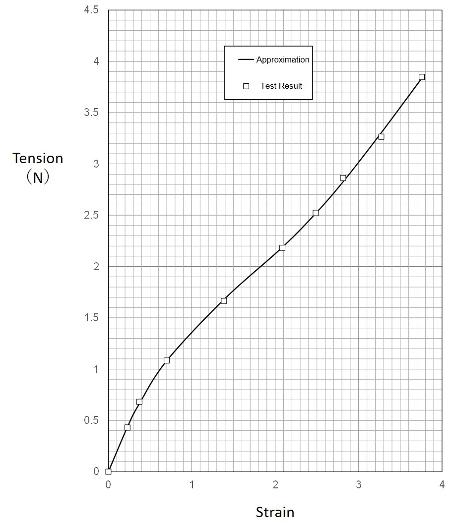
Fig. 7 Stress-Strain Curve of Rubber
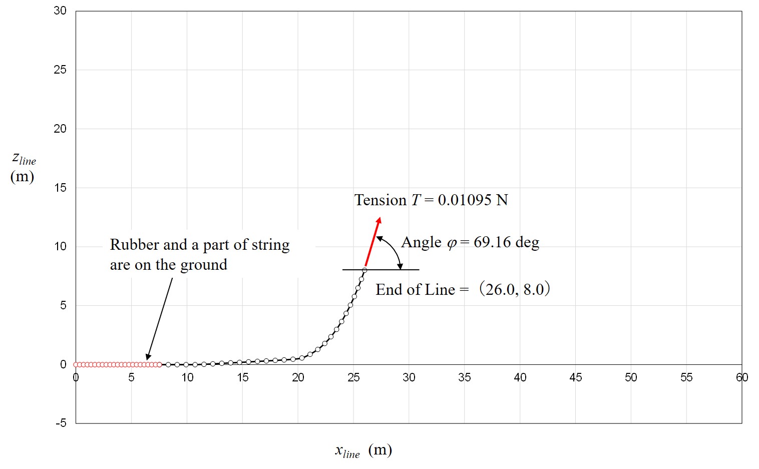
Fig. 8 Example of Line Analysis Result
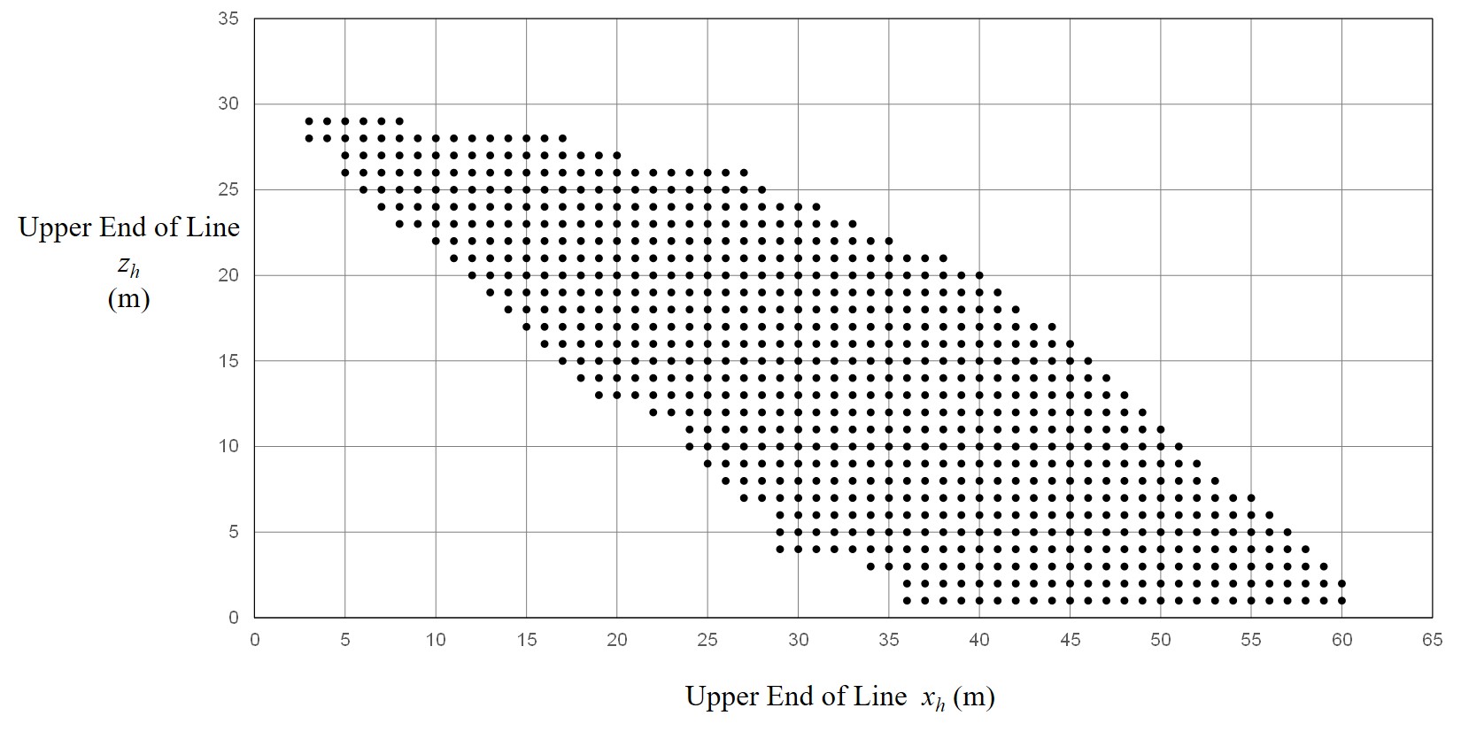
Fig. 9 Calculation Points
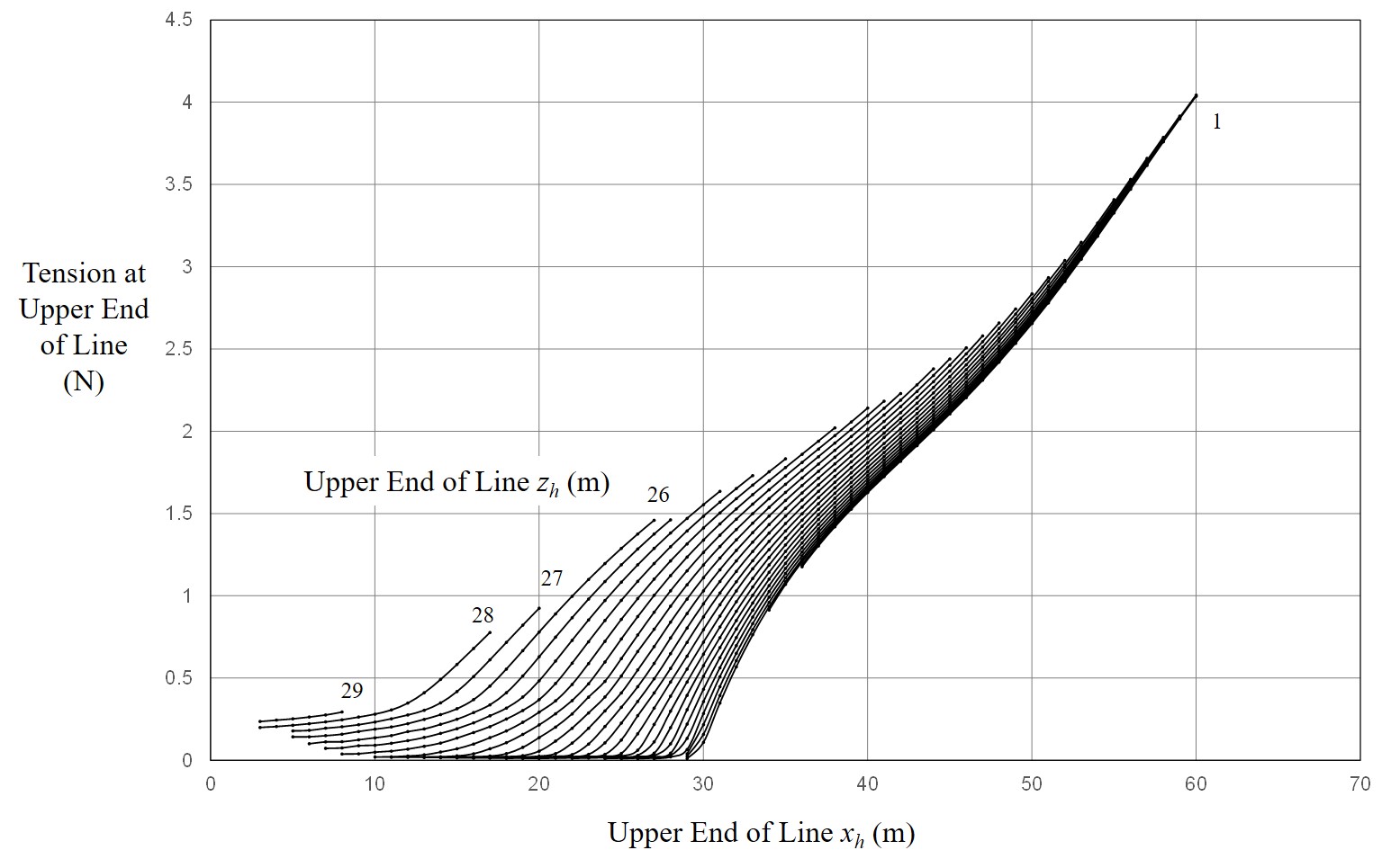
Fig. 10 Location of Upper End of Line and Tension
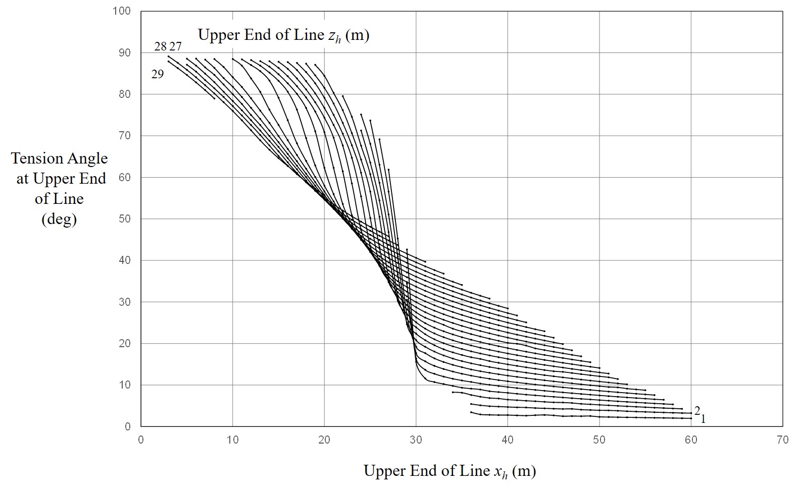
Fig. 11 Location of Upper End of Line and Tension Angle
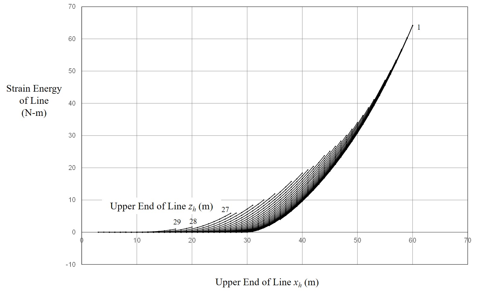
Fig. 12 Location of Upper End of Line and Total Strain Energy
3.2.4 Approximate Equations for Line Tension and Its Angle
When solving the equation of motion of the glider during high-start launch, it is necessary to read the tension of the line and their angles from the curves in Figs. 10 to 12, but these curves have complex shapes, so interpolation is troublesome. Therefore, the author decided to approximate the curves in Figures 10 through 12 using an artificial neural network. A schematic diagram of the artificial neural network used is shown in Figure 13.
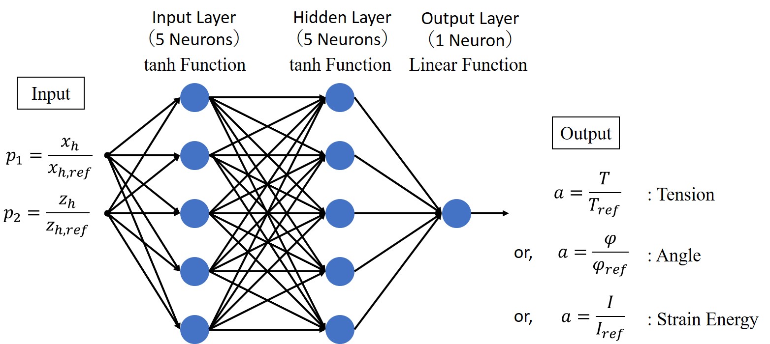
Fig. 13 Artificial Neural Network Used for Approximation of Figures 10 to 12
3.3.3 Equation of Motion of Glider
3.3.1 Forces Acting on the Glider
The forces acting on the glider are shown in Figures 14 and 15. The position of the hook is shown in Figure 16. The hook is offset laterally from the center line of the fuselage. The hook is open downwards to make it easier for the glider to detach from the line.
Gravity and aerodynamic forces act on the center of gravity of the glider.
The tension of the line, the gravity of the marker, and the drag force of the marker act on the hook.

Fig. 14 Forces Acting on Glider Except for Aerodynamic Forces
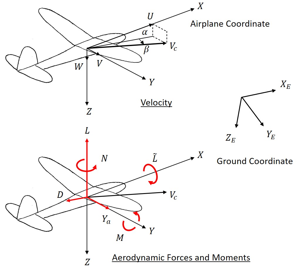
Fig. 15 Aerodynamic Forces and Moments Acting on Glider
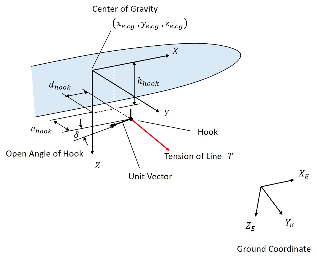
Fig. 16 Hook Position and Configuration
3.3.2 Equation of Motion
Using the forces shown in the previous section, the equations of motion around the center of gravity of the glider are derived according to References [3] and [4].
3.3.3 Calculation of Aerodynamic Coefficients of Glider
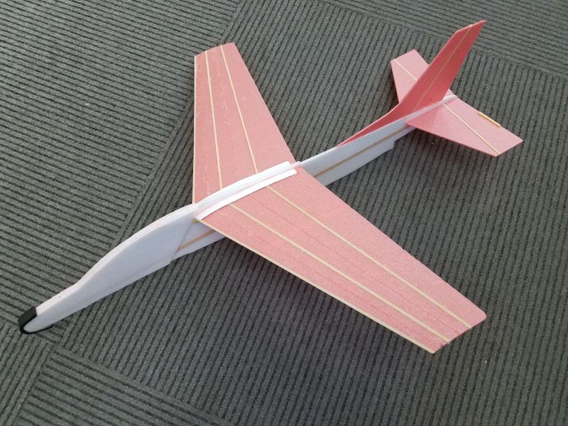
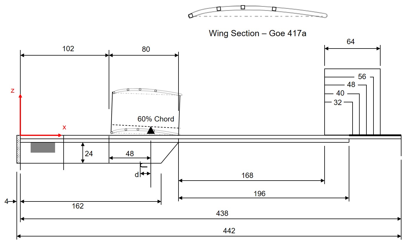
Figures 17 and 18 show the glider to be analyzed. The main materials used were cypress rods and 2mm thick styrofoam sheet.
The wing area is 48,000 sq.mm, the wing span is 600 mm, and the total mass (actual measurement) is 31 grams. The wing dihedral angle and vertical stabilizer area were varied.
The aerodynamic coefficients were calculated using the vortex lattice method program "AVL". Figure 19 shows the AVL model of the glider. The total lift coefficient during steady glide is assumed to be 0.8.
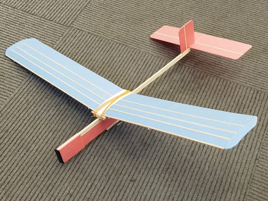
Fig. 17 Glider to be Studied
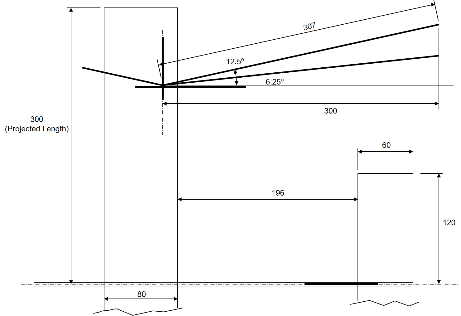
The height of the vertical stabilizer was assumed to be 1.2 times the width.
Fig. 18 Drawing of Glider
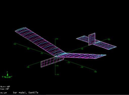
Fig. 19 AVL Model of Glider
3.3.4 Inertia Properties of Glider
The inertia properties of the glider was calculated based on the drawings. The calculated values of the center of gravity and the mass were in close agreement with the measured values.
3.3.5 Solving Equations of Motion
"Octave" was used to solve the equations of motion.
3.3.4 Release Condition from Line
The forces acting on the hook from the line are the tension of the line, the drag force of the marker, and the weight of the marker. The combined force of these forces is obtained, and this combined force is transformed in the direction of the angle of the hook (Figure 20).
When the force component parallel to the hook acts backward and the force is greater than the frictional force, the ring at the end of the line slips and the ring is released from the hook. This is the condition for the release of the glider from the line.
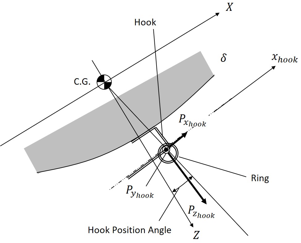
Fig. 20 Forces Acting on Hook
4. Results of Motion Analysis
4.1 Example of Analysis Results
Figure 21 shows an example of analysis results.
The configuration of the glider are as follows:
- Wing Dihedral Angle: 12.5 deg.
- Vertical Stabilizer Dimension: 48 × 57.6 mm
- Hook Position Angle: 10 deg. (see Figure 20 for the definition of hook position angle).
- The glider is launched with the rubber stretched 15 meters and the glider tilted 10 degrees to the left around the roll axis.
The glider ascends while turning in the direction of tilting, but changes direction midway and returns to the direction of the stake. The glider detached from the line a little past the highest point. The detached point is 13 meters in front of the stake. The velocity reaches 11 m/s immediately after launch, and then gradually decreases. At the release, the velocity is almost the same as the glider's steady-state glide speed, 4.0 m/s. The trajectory in Figure 21 is qualitatively the same as the trajectory when the aircraft is actually flown.
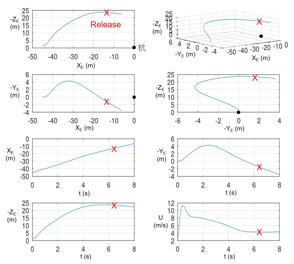
Fig. 21 Example of Analysis Result
4.2 Investigation of Stability in Hi-start Launch
The effects of the hook position and the lateral stability of the glider on the high-start launch were investigated.
(1) Effects of Wing Dihedral Angle and Vertical Stabilizer Area
The case of a launch with the rubber extended 15 meters and the glider tilted 5 degrees to the right around the roll axis was analyzed.
Figures 22 and 23 show the results of a comparison of the vertical stabilizer area for the wing dihedral angle of 6.25 degrees (small) and 12.5 degrees (large), respectively.
The hook position angle was fixed at 15 degrees.
When the vertical stabilizer area is too small, the glider meanders violently, and when the vertical stabolizer area is too large, the aircraft plunges into the direction of tilting. Too large a vertical stabilizer area results in too much stability, while too small a vertical stabilizer area results in too little stability.
A small dihedral angle results in a small appropriate vertical stabilizer area, while a large dihedral angle results in a large appropriate vertical stabilizer area.
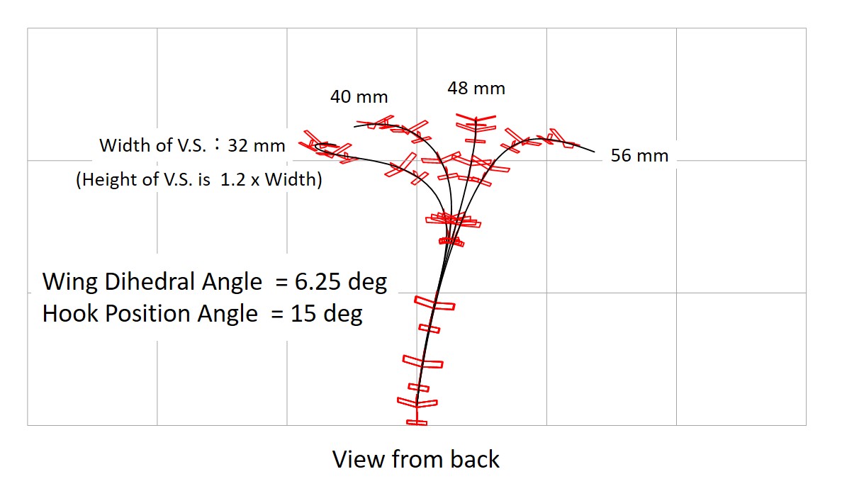
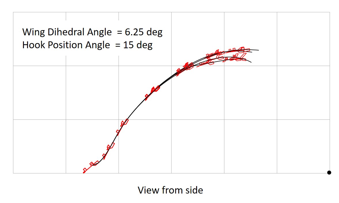
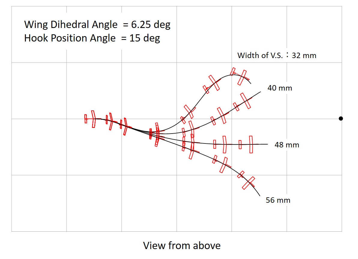
Fig. 22 Start with 5 deg. Tilting, Wing Dihedral 6.25 deg. (grid:10 meters)
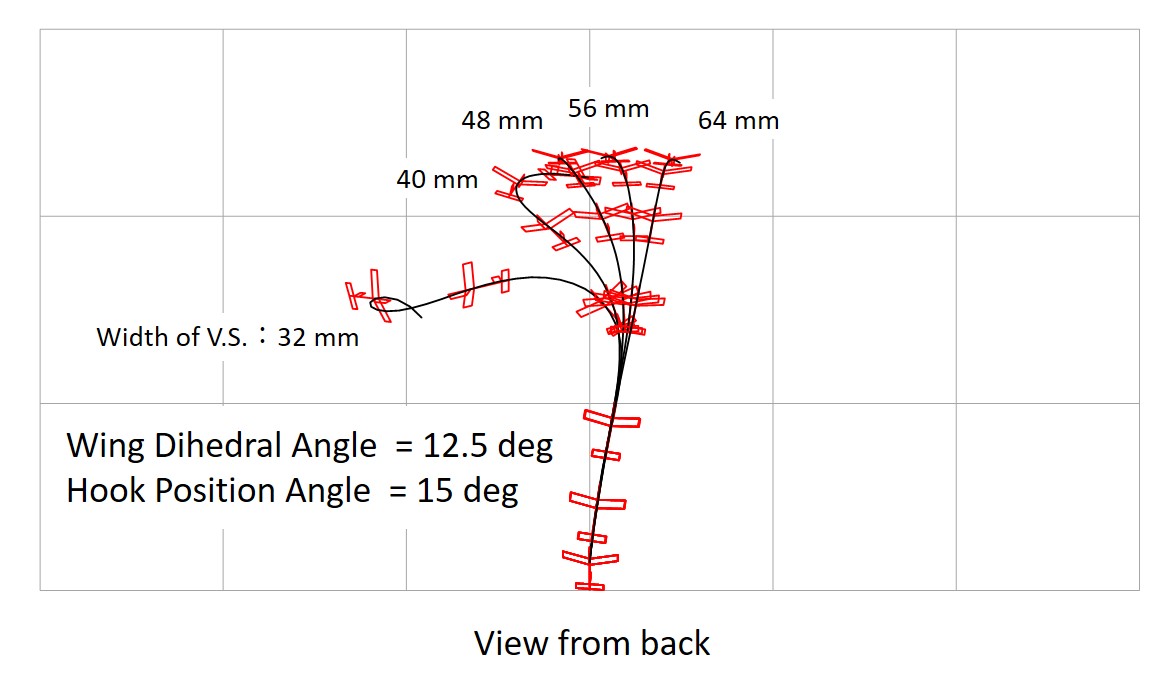
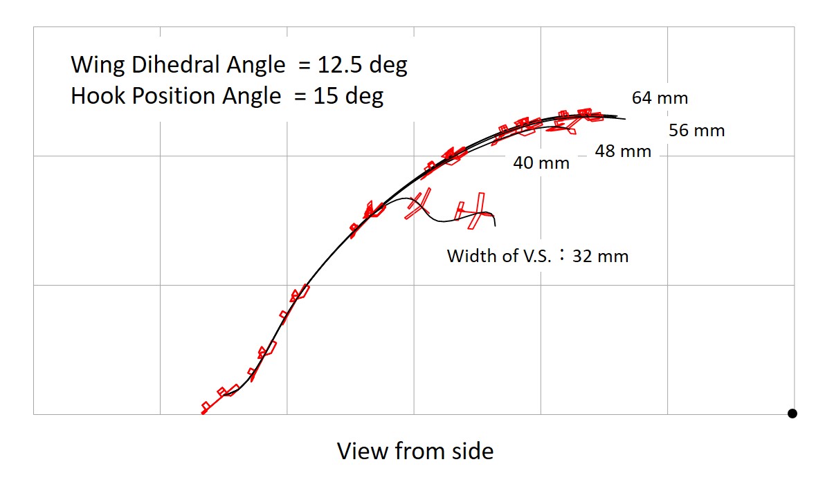
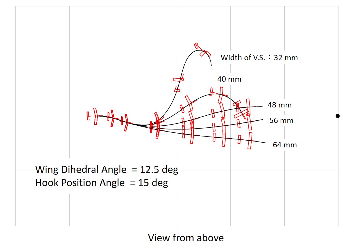
Fig. 23 Start with 5 deg. Tilting, Wing Dihedral 12.5 deg. (grid:10 meters)
(2) Effect of Hook Position
The case of an glider with a turning tendency (with rudder angle) that makes a left turn with a radius of 30 meters was analyzed. The effect of hook position was examined for an gider with an appropriate vertical stabilizer area.
The vertical stabilizer area was 40 × 48 mm for a glider with a wing dihedral of 6.25 degrees (small) and 48 × 57.6 mm for a glider with a wing dihedral of 12.5 degrees (large). Figure 24 and Figure 25 show the results of a comparison of motions by changing the hook position angle.
When the hook is set forward, the glider tends to return to its course and meanders more violently. Conversely, when the hook is moved backward, the path does not return. The smaller the dihedral angle, the larger the appropriate hook position angle (hook forward). For stable launch, the hook position angle should be set so that the aircraft meanders slightly.
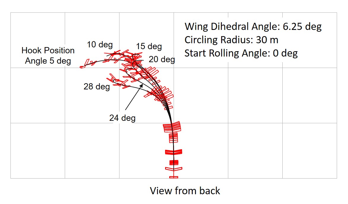
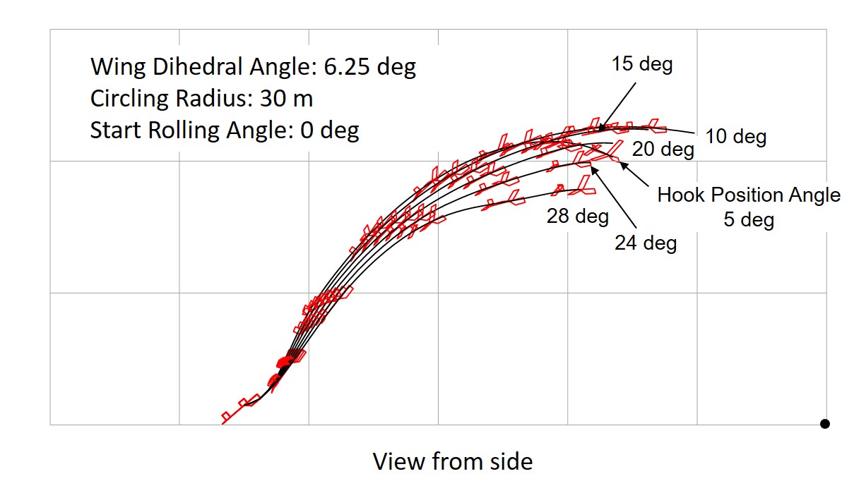
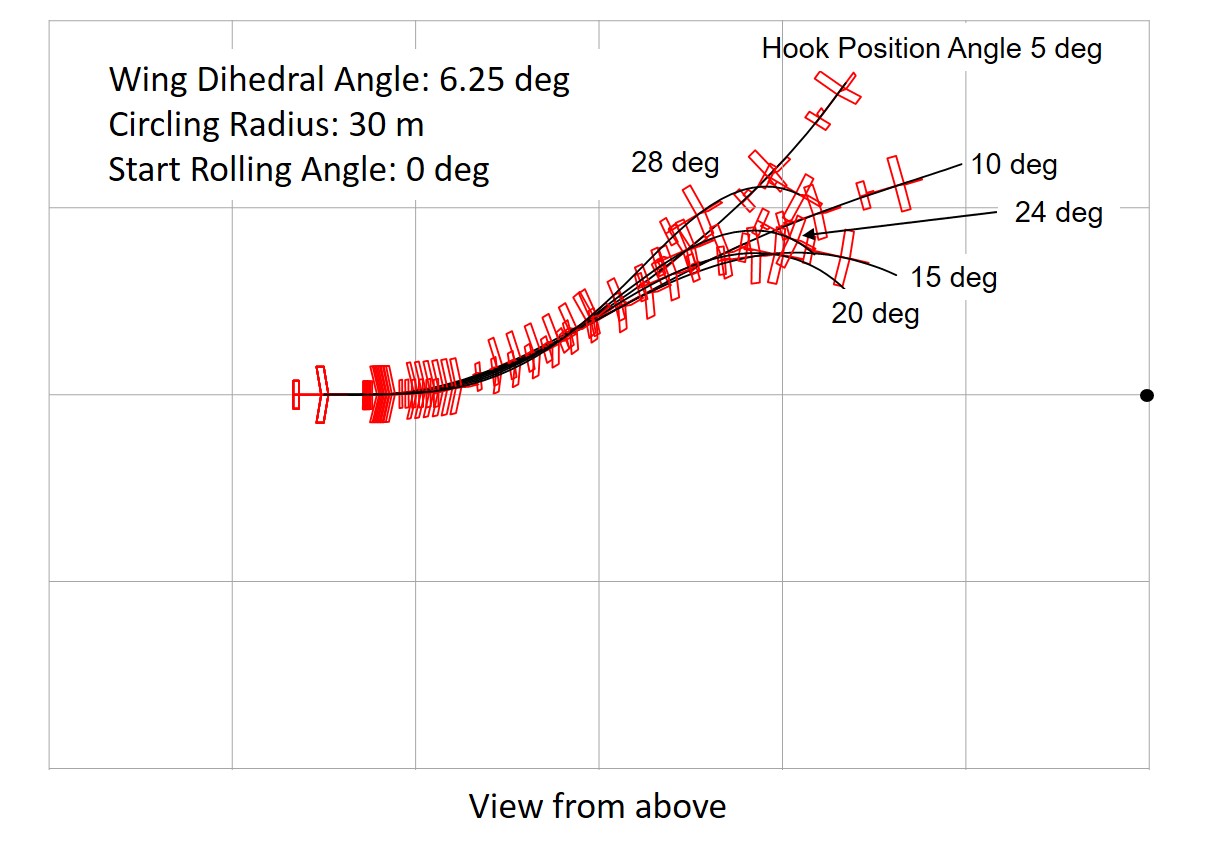
Fig. 24 Effect of Hook Position With Left Turn Tendency, Wing Dihedral 6.25 deg. (grid:10 meters)
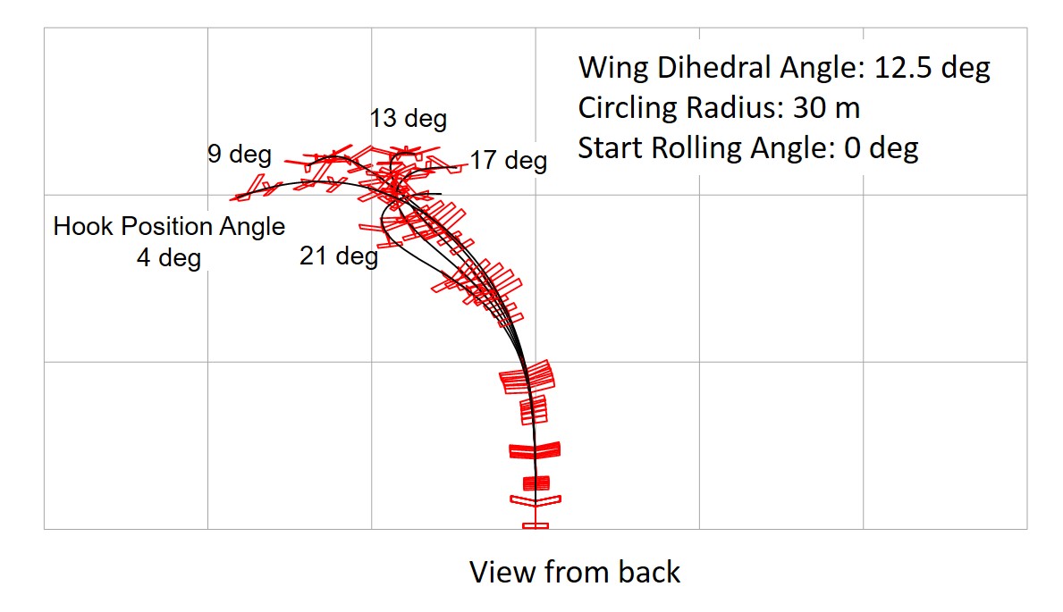
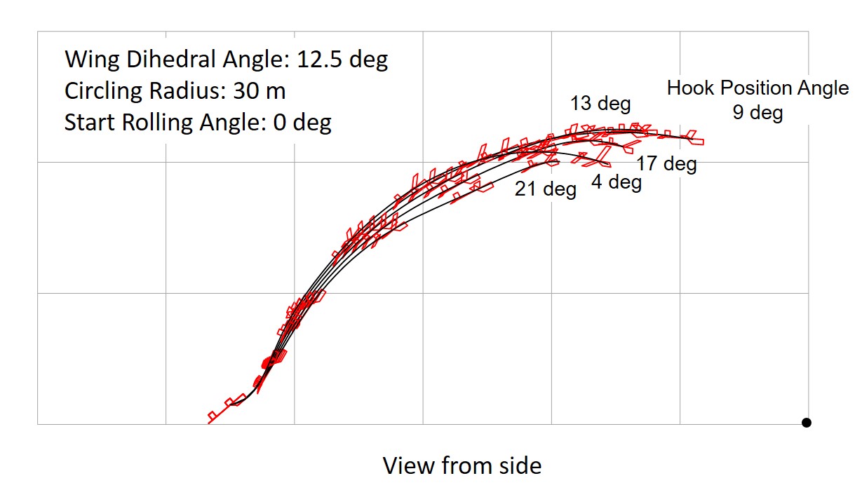
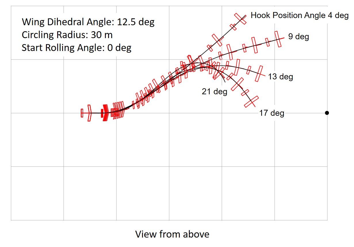
Fig. 25 Effect of Hook Position With Left Turn Tendency, Wing Dihedral 12.5 deg. (grid:10 meters)
(3) Realization of Circling Flight
Free-flight model gliders need to turn in order to stay in the thermals longer and to make it easier to retrieve the glider. Generally, auto-rudder is used to achieve both straightness during launch and turning after launch. Auto-rudder can be used in hi-start launch, but it is difficult to equip small gliders with it.
Other methods of turning that can be used for hi-start launching include:
- utilize inherent stability of the glider (hook at center line)
- utilize offset hook (Figure 26)
= Utilizing Inherent Stability of Glider =
As shown in Figures 24 and 25, hi-start launch is possible even when the glider has a certain degree of turning tendency. In the glider shown in Figure 18, a turning radius of about 30 meters is possible with dihedral angle of 12.5 degrees and a vertical stabilizer of 48 x 57.6 mm. The hook position angle of about 13 degrees is optimal. The glider is characterized by its meandering ascent at hi-start. Conversely, this method cannot be used unless the glider has tendency of meandering.
= Using an Offset Hook =
Using an offset hook on the same glider as in the previous section, the turning radius can be reduced to 15 meters with changing rudder angle. The hook position angle is 8 degrees and the offset is 7 mm from the centerline in the direction of the turn. The meandering is reduced. The use of an offset hook increases the altitude gained. It was found that the offset hook can be used only for gliders with large dihedral angle.
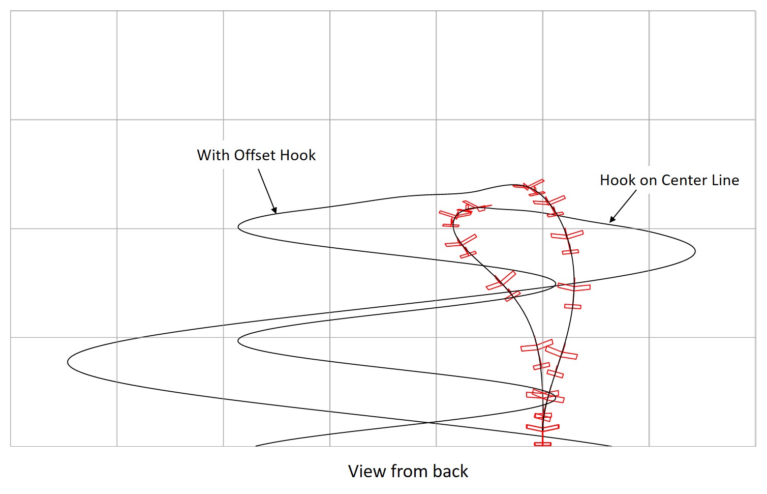
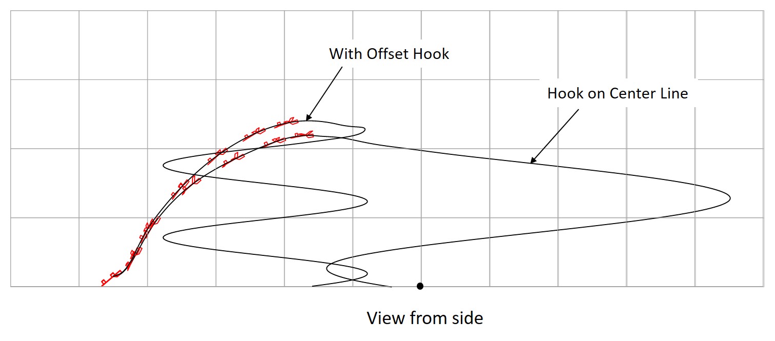
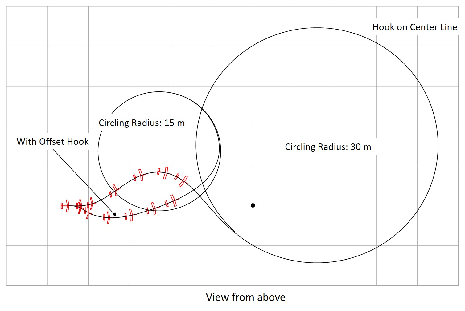
Fig. 26 Circling Flight after Hi-start Launch
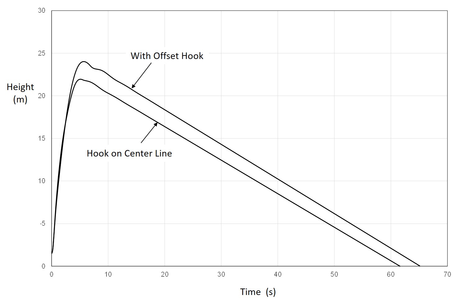
Fig. 27 Comparison of Altitude in Hi-start Launch, With and Without Offset Hook
4.3 Findings on Trimming of Hi-start Glider
(1) Initial Position of Hook
The hook is installed at approximately 15 degrees forward from the center of gravity (Figure 20). For easy confirmation, hang the glider upside down at the hook position so that the angle between the axis of the fuselage and the horizontal line is approximately 15 degrees.
(2) Hand-thrown glide adjustment of glider
First, the glide is adjusted by hand-throwing the glider so that it glides straight and steady.
(3) Trial high-start launch
Perform a high-start launch without tilting the glider to the left or right. The rubber should be stretched to about 10 meters.
- If the glider climbs straight up, it is OK. Go to (4)
- If the glider does not climb straight and turns to the left or right, there is a high possibility that it has a tendency to turn.
In this case, correct the warping of the wings and the fuselage.
If the glider does not have a tendency to turn, move the hook forward, moving the hook about 2 mm at a time.
- If the meander is small, go to (4).
- If the meandering is large, move the hook backward, moving the hook about 2 mm at a time.
- If the hook comes off during ascent and the glider stalls as it raises its nose, the hook opening angle is too large. Reduce the hook opening angle (Figure 16).
- If the glider rotates in a circular motion (as in the case of the vertical stabilizer with a 40 mm width shown in Figure 23), either the vertical stabilizer area is not large enough or the wing dihedral angle is too large.
- If the glider climbs in a straight line or meanders slightly, but the hook does not release even after reaching the highest point, the hook opening angle is too small.
(4) Tilt the glider 5 degrees at start of hi-start
Tilt the glider about 5 degrees around the roll axis at launch.
- It is recommended that the glider meanders a little during ascending (as Figure 23 for vertical stabilizer with a width of 40 to 56 mm).
- If the meander is too large, move the hook backward.
- If the glider does not return to the direction of the stake, either the dihedral angle is not enough or the vertical stabilizer is too large (as in the case of a vertical stabilizer with a width of 56 mm as shown in Figure 22).
(5) Turning method
The author uses the following turning methods:
Inherent stability, Offset hook, Detachable fin, or Autorudder.
5. Summary
Three dimensional motion analysis of hi-start launch of model glider was presented, and the motion of a model glider was investigated.
The stability of the hi-start launch was investigated by examining the effects of the wing dihedral angle, vertical stabilizer area, and hook position. Useful findings were obtained.
The author plans to verify the validity of the analysis through the flight test of model gliders.
References
[1] F. Zaic, "Model Glider Design," Model Aeronautic Publications, New York, 1944.
[2] 滝敏美,町田光生,「フリーフライト模型グライダーのハイスタート発進の解析」,第 26 回スカイスポーツシンポジウム,JSASS-2021-6008,2021 年.
[3] 加藤寛一郎,大屋昭男,柄沢研治,「航空機力学入門」,東京大学出版会,1982 年.
[4] 金田弥奈,加藤寛一郎,「模型航空機の最長時間滞空について」,日本航空宇宙学会誌,第 39 巻,第 453 号(1991 年 10 月),pp.539-544.
[5] M. Drela and H. Youngren, "AVL 3.36 User Primer," 2012.
[6] 松田七美男,「Octave の精義(第2版)」,カットシステム,2019 年.