Telescope Making
Making 8-inch Newtonian Reflector
 to Japanese/“ú–{Śę‚Ö
Written by Toshimi Taki
November 2, 2003
Revised on November 8, 2003
Revised on November 15, 2003
Revised on January 1, 2004
Revised on January 24, 2004
Revised on October 11, 2004
Revised on September 3, 2006
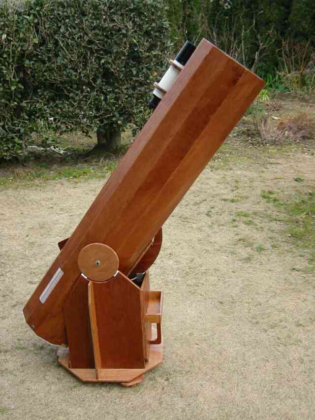
8-inch Newtonian on Dobsonian Mount

Photographs of The Moon Taken with My 8-inch Telescope
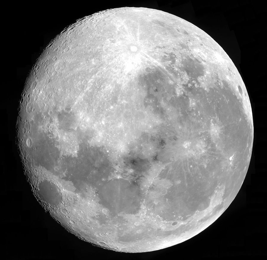
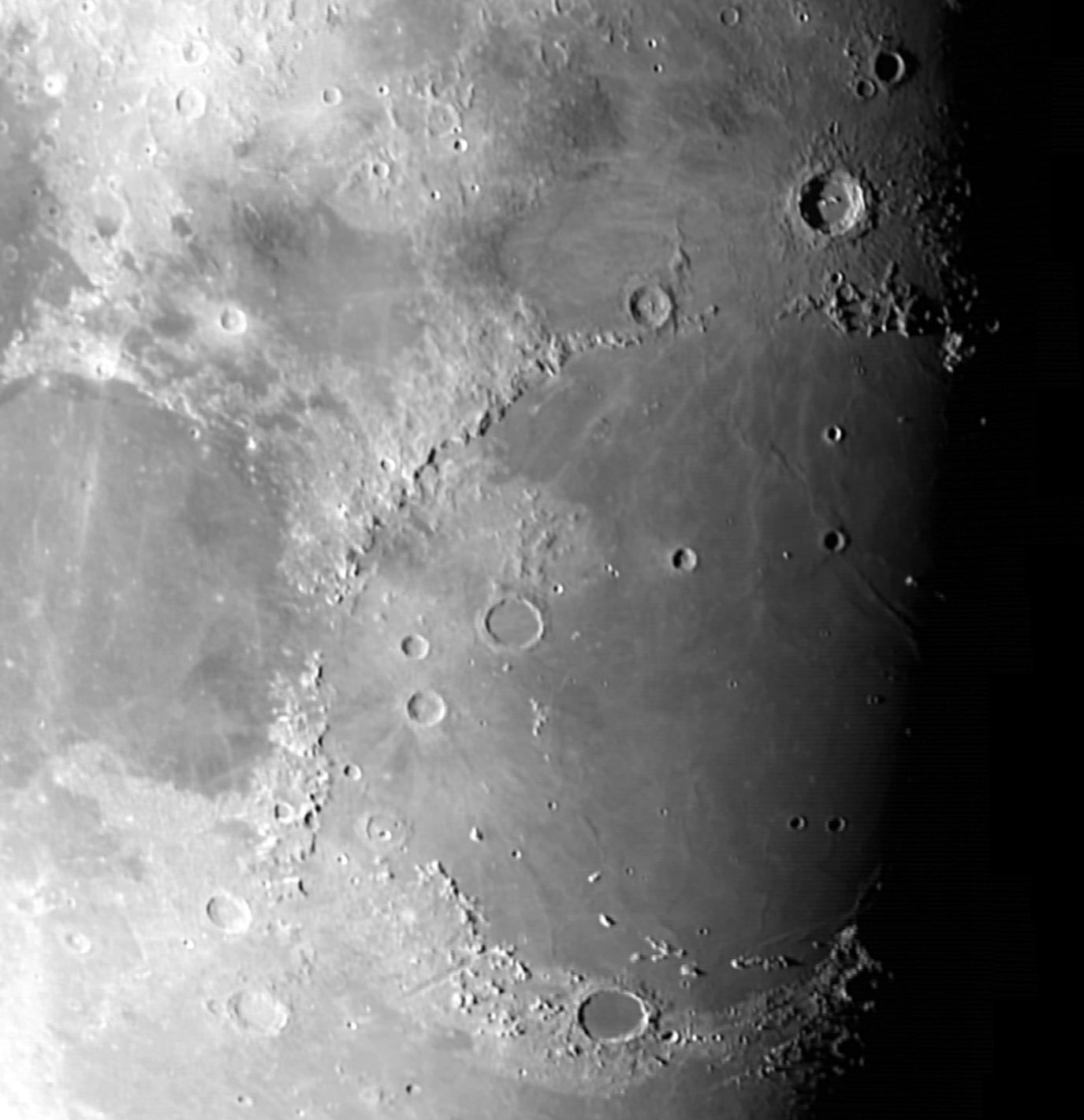
Table of Contents
1. Introduction
2. Specification
3. Optics
4. Tube Assembly
4.1 Construction of Tube
4.2 Mirror Cell
4.3 Secondary Mirror Holder/Spider
4.4 Focuser
4.5 Finder and Its Support
4.6 Tube Assembly
4.7 Collimation
4.8 Star Test (New)
5. Mounting
5.1 Dobsonian Mount
1. Introduction
I own a 12.5-inch, f/6 Dobsonian telescope for over ten years and I realize that it is too big for me. I need a ladder to reach the eyepiece when the telescope is aimed near the zenith. Transportation is not so easy because of its weight. I usually use the 12.5-inch at public observing sessions and it is very dangerous for children to reach the eyepiece with a ladder.
I decided to build a new telescope. I will use the telescope for observation of the planets and the Moon from my light poluted backyard and for public observing sessions. The telescope should have the following features.
- Possible to see the zenith without ladder
- High optical quality
- Light weight for easy transportation
- Stiffness
- Easy to assemble
- Equatorial mount and Dobsonian mount
..... Equatorial mount for serious observation and Dobsonian mount for casual star watching.
Return to Table of Contents
2. Specification
In order to realize the features above, I chose an 8-inch, f/6 Newtonian. I bought a primary mirror and a secondary mirror from Parks Optical, because Parks has a good reputation of optical quality. Specification of the telescope is as follows.
- 8-inch, f/6 Newtonian reflector
-- Tube assembly
........... Closed tube construction
........... 3-point support cell for primary mirror
........... Curved vane spider
........... Crayford focuser
........... 7x 50mm finder
........... Wooden construction
-- Dobsonian Mount
........... Similar design as shown in chapter 13 of "The Dobsonian Telescope" by Kriege and Berry.
-- Equatorial Mount
........... Fork-type equatorial mount
........... Provision for motor drive in future upgrade
........... Tube assembly rotation for comfortable eyepiece position
........... Wooden construction
-- Weight
........... Tube assembly including finder:...... 7.8 kg
........... Dobsonian mount:.....................................4.2 kg
........... Total (Dobsonian configuration) : 12.0 kg
Return to Table of Contents
3. Optics
(1) Primary Mirror
- Diameter ................ 8.00 inches (203 mm)
- Focal length ........ 48.7 inches (1237 mm)
- Focal ratio .............. f/6.09
- Thickness ............... 36mm
- Weight ........................ 2.63kg
- Manufactured by.... Parks Optical
- S/N ................................ 864870627001281
(2) Secondary Mirror
- Minor axis ............................ 1.83 inches (46.5 mm)
- Thickness ................................ 12mm
- Weight ....................................... 0.060kg
- Manufactured by ............ Parks Optical
- Central Obstruction ....... 23%
Return to Table of Contents
4. Tube Assembly
4.1 Construction of Tube
I designed the tube light and stiff. The tube is a frame-and-panel construction made from 3mm (1/8 inch) thick plywood. The construction is similar to the aircraft fuselage structure. The size of the tube is 265mm outer diameter by 1300mm long. It weighs only 2.5 kg (5.5 lbs). You don't need special tool or jig to build the tube. If you make a tube with aluminum (245mm dia. x 2mm thick x 1300mm long), it will weigh 5.6 kg (12.4 lbs).
Completed tube after painting.

The frame is devided to 3 parts. Inner opening is 240 mm in diameter.

Side panels and frames. Panel size is 70mm wide by 1300mm long.

3 panels and 5 frames are bonded together with epoxy adhesive. This building method is "tack-and-glue" method usually used in boat building.

2 additional panels are bonded to a 3-panel shell. Note that stiffeners and subframes are added at a door opening. The door is cut out after adhesive is cured.


Door cutout is made in 5-panel shell.

3-panel shell and 4-panel shell are bonded together.

7-panel shell, 5-panel shell and a door.

7-panel shell and 5-panel shell are bonded together. The tube is waiting for painting.

Return to Table of Contents
4.2 Mirror Cell
The mirror cell is made of 12mm thick plywood. The cell consists of a circular plate and a triangular base. Circular holes in the plates are for weight reduction and ventilation. The 8-ich mirror is bonded on the circular plate with silicon rubber adhesive at 3 points on 40% radius of the mirror. 40% radius is the optimum location for 3-point support cell. I added three wooden blocks around the mirror in order to prevent the mirror from falling off in case the bonding between the mirror back and the cell fails. Silicon rubber adhesive was also applied to the gaps (5mm) between the blocks and the side of the mirror.
3 pairs of push-pull bolts (M5) are provided for collimation.
Parts of mirror cell.

Front view of mirror cell assembly. Mirror cell weighs 520 grams before painting.

Back side of mirror cell assembly.

Mirror installation to the cell. Note that three wooden blocks are added for lateral support.

Return to Table of Contents
4.3 Secondary Mirror Holder/Spider
The secondary mirror holder and the curved vane spider are made of hardwood, aluminum sheet and aluminum plate. The secondary mirror is bonded to a hardwood block with silicon rubber adhesive. 3 screws are used to adjust the tilt of the secondary mirror.
The secondary mirror holder/spider without a mirror weighs about 120 grams.
Parts before painting.

Mirror holder assembly.

Curved vane before painting.

Close-up of mirror holder and adjustment device.


Secondary mirror is installed to the spider.

Return to Table of Contents
4.4 Focuser
I made a simple crayford focuser shown in the photograph below. It weighs only 150 grams. See "Poor Man's Crayford Focuser" in my homepage for design detail.

Return to Table of Contents
4.5 Finder and Its Support
I use 7x 50mm finder which I bought 30 years ago from Takahashi. I made finder supports from 3mm thick plywood as shown in the photographs below. Threaded inserts are embedded in the support rings for adjustment bolts. The forward support has two adjustment bolts and the rear support has three adjustment bolts.
Rear support before sanding. 4 plies of 3mm thick plywood are bonded together.


7x 50mm Finder and supports. Total weight is 420 grams.

Return to Table of Contents
4.6 Tube Assembly
The mirror cell, the spider and the focuser were installed to the tube on December 29, 2003. The weight of the tube assembly without finder supports and finder is 6.0kg.
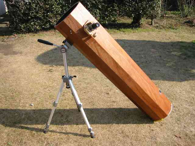
The first light of the telescope was on December 30, 2003 on a temporary mount.
Tube assemply on a temporary mount.
Tube assembly (1/3)

Tube assembly (2/3)

Tube assembly (3/3)

Spider is installed to tube.

Finder supports, finder and focuser are installed to tube assembly.

Tube assembly -- door open

Tube assembly -- door closed

Return to Table of Contents
4.7 Collimation
I made a sightt tube from 1.25 inch O.D. x 6 inch long brass tube. I installed two wires at one end of the tube and a film can cap with a small hole at the center to another end.
Sight tube (1/2)

Sight tube (2/2)

Sight tube installed to tube assembly

Seeing through focuser.

Return to Table of Contents
4.8 Star Test
I took photographs of de-focused star images on September 2, 2006. The star is Polaris.
Judgement:
(1) There is still slight misalignment.
(2) Very slight overcorrection.

Data: Photographs taken at 21h10m - 21h13m, September 2, 2006. 2x Barlow, Philips SPC900NC Webcam.
Reference: H. R. Suiter, "Star Testing Astronomical Telescopes - A Manual for Optical Evaluation and Adjustment," Willmann-Bell, Inc., 1994.
Return to Table of Contents
5. Mounting
5.1 Dobsonian Mount
The main material for the Dobsonian mount is 12mm thick plywood. Altitude bearings are a 225mm radius semi-circular plate and a 75mm radius circular plate. The eyepiece hight aimed at the zenith is 1220mm. The Dobsonian mount was completed on January 24, 2004.
8-inch Newtonian on Dobsonian mount (1/2).
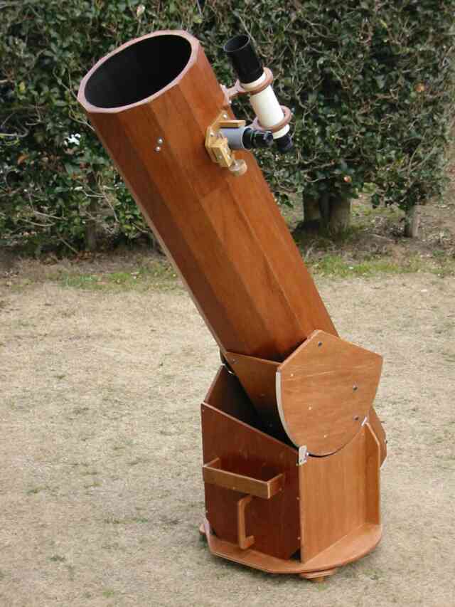
8-inch Newtonian on Dobsonian mount (2/2).
Rocker and ground board (1/2). You can see a shelf for eyepieces and a carrying handle in the front board of the rocker.

Rocker and ground board (2/2).

Ground board. Note that additional pads are installed around the pivot bolt in order to reduce friction of azimuth movement.

Backside of ground board. Feet are made of hardwood.

Altitude bearing keeper at front end of side board.

Altitude bearing (1/2).

Altitude bearing (2/2).

Altitude bearing support is added to improve stiffness of the large altitude bearing plate.

Return to Table of Contents